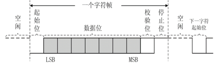
前两贴我们实现了uart的发送模块,这一贴我们实现一下接收模块。通信接收端往往比发送端要复杂,因为要考虑各种外部情况,尽可能的在外部有一定干扰的情况下也能接收完整的数据,可做的设计就比较多。此贴我们先做一个简单的情况,通讯参数固定。uart字符帧格式:
代码如下:
uart_core 顶层文件:
module uart_core #
(
    parameter SIM_DEBUG = "FALSE",          // "TRUE"  "FALSE"
    parameter BAUD      = 115200,             // 波特率
    parameter CLK_F     = 50_000_000        // 时钟频率
)
(
    input  clk,

    input  rx,
    output tx,

    input  rst
);

wire busy;
reg [7:0] tx_cnt;

reg [7:0] tx_data = 0;
reg tx_en = 0;
wire [7:0] rx_data;
wire rx_done;

reg [2:0] tx_st = 0;
always @ (posedge clk)
if(rst)
begin
    tx_data <= 0;
    tx_en <= 0;
    tx_st <= 0;
end
else case (tx_st)
0:
begin
    tx_cnt <= 0;
    tx_data <= 0;
    tx_en <= 0;

    if(SIM_DEBUG == "TRUE") tx_st <= 1;
    else if(rx_done)
        tx_st <= 1;
end
1:
begin
    if(!busy)
    begin
        tx_data <= (SIM_DEBUG == "TRUE") ? tx_data + 1 : rx_data;
        tx_en <= 1;
        tx_st <= 2;
    end
end
2:
begin
    tx_en <= 0;
    tx_st <= 3;
end
3:
begin
    tx_cnt <= tx_cnt + 1;

    tx_st <= (SIM_DEBUG == "TRUE") ? 1 : 0;

end
endcase


`define NONE    0
`define ODD     1
`define EVEN    2
`define MARK    3
`define SPACE   4

`define STOPBIT_ONE     0
`define STOPBIT_ONEHALF 1
`define STOPBIT_TWO     2

uart_tx #
(
    .BAUD      (BAUD),
    .CLK_F     (CLK_F),
    .PARITY    (`NONE),
    .DATABITS  (8),
    .STOPBIT   (`STOPBIT_ONE)

)
uart_tx_inst
(
    .clk    (clk),

    .tx     (tx),

    .data   (tx_data),
    .enable (tx_en),
    .busy   (busy),  // 指示外部调用模块,在忙的时候,不接收新的数据

    .rst    (rst)
);


uart_rx #
(
    .BAUD      (BAUD),
    .CLK_F     (CLK_F)
)
uart_rx_inst
(
    .clk    (clk),

    .rx     (rx),

    .data   (rx_data),
    .done   (rx_done),  // 指示外部调用模块,在忙的时候,不接收新的数据

    .rst    (rst)
);

endmodule
uart_rx.v
module uart_rx #
(
    parameter BAUD      = 9600,             //波特率
    parameter CLK_F     = 50_000_000        //时钟频率
)
(
    input wire clk,
    input wire rst,
    input wire rx,

    output reg [7:0] data,
    output reg done //接收完成提示
);

localparam [31:0] CNT_MAX = CLK_F / BAUD;

//【1】检测起始位
reg [1:0] rx_r;

always@(posedge clk or posedge rst)
begin
    if(rst)
        rx_r <= 0;
    else
    begin
        // rx_r[0] <= rx;
        // rx_r[1] <= rx_r[0];

        rx_r<={rx_r[0], rx};
    end
end

wire en; //起始位信号
assign en = (rx_r == 2'b10) ? 1'b1 : 1'b0;

//【2】使用状态机来接收rx线上的数据

//[1] 定义状态空间
localparam FSM_IDLE    = 0; //空闲状态
localparam FSM_START   = 1; //接收起始位状态
localparam FSM_DATA    = 2; //接收数据位
localparam FSM_PARITY  = 3; //接收校验位
localparam FSM_STOP    = 4; //接收停止位

//[2] 定义状态变量
reg [2:0] cstate;

//[3] 实现状态机
//每个状态做状态判断和跳转,以及根据状态输出

reg [7:0] data_r;
reg [31:0] cnt;
reg startbit;
reg [3:0] num;

always@(posedge clk or posedge rst)
begin
    if(rst)
    begin
        cstate <= 0;
        data_r <= 0;
        num <= 0;
        done <= 0;
        cnt <= 0;
        startbit <= 0;
    end
    else
    case(cstate)
        FSM_IDLE :
        begin
            done <= 0;
            if(en)
            begin
                cstate <= FSM_START;
                cnt <= 0;
            end
            else
                cstate <= FSM_IDLE;
        end

        FSM_START :
        begin
            cnt <= cnt + 1;

            if(cnt == CNT_MAX[31:1] && rx_r[1])
                cstate <= FSM_IDLE ; //收到开始位为1 ,说明前面是个干扰信号
//            else if( rx_r[1] == 0 && cnt == CNT_MAX - 1 )
            else if( cnt == CNT_MAX - 1 )
            begin
                cstate <= FSM_DATA; //收到开始位为0 ,是起始位
                cnt <= 0;
            end
        end

        FSM_DATA :
        begin
            cnt <= cnt + 1;

            if(cnt == CNT_MAX[31:1] ) //bit位中点时采集数据
                data_r[num] <= rx_r[1];

            if(cnt == CNT_MAX - 1 && num <= 8-1)//bit位计数完毕,但数据位还没收满8个
            begin
                num <= num + 1;
                cnt <= 0;
            end
            else if(num == 8) //数据位收满8个
            begin
                cstate <= FSM_STOP; //无校验直接跳到FSM_STOP状态
                cnt <= 0;
                num <= 0;
            end
        end

        FSM_STOP :
        begin
            cnt <= cnt + 1;

            if(cnt == CNT_MAX[31:1] )
            begin
                cstate <= FSM_IDLE;
                data <= data_r; //接收到的数据发送到端口
                done <= 1; //接收完成标志信号拉高
                cnt <= 0;
            end
            else
                cstate <= FSM_STOP;
        end

        default :
        begin
            cstate <= 0;
            data_r <= 0;
            num <= 0;
            done <= 0;
            cnt <= 0;
            startbit <= 0;
        end
    endcase

end

endmodule
uart_tx.v
`define NONE    0
`define ODD     1
`define EVEN    2
`define MARK    3
`define SPACE   4

`define STOPBIT_ONE     0
`define STOPBIT_ONEHALF 1
`define STOPBIT_TWO     2

module uart_tx #(
    parameter BAUD      = 9600,             //波特率
    parameter CLK_F     = 50_000_000,       //时钟频率
    parameter PARITY    = `ODD,             //校验方式
    parameter DATABITS  = 8,                //数据位长度
    parameter STOPBIT   = `STOPBIT_ONEHALF  //停止位长度
)
(
    input wire clk,
    input wire rst,
    input wire [ DATABITS - 1: 0 ] data,
    input wire enable,

    output reg tx,
    output reg busy //指示外部调用模块,在忙状态时候,不能接受新的数据
);

localparam [31:0] CNT_MAX = CLK_F / BAUD;

// 【1】缓存外部数据 data

reg [ DATABITS - 1 : 0 ] data_r;

always@( posedge clk or posedge rst )
begin
if ( rst )
    data_r <= 0;
else if ( enable && busy == 0 )
    data_r <= data;
else
    data_r <= data_r;
end

//【2】用状态机来完成发送
reg [ 31: 0 ] cnt;
reg [ 3: 0 ] num;
//[1] 定义状态空间
localparam FSM_IDLE     = 0; //空闲状态
localparam FSM_START    = 1; //起始位状态
localparam FSM_DATA     = 2; //数据位状态
localparam FSM_PARITY   = 3; //校验位状态
localparam FSM_STOP     = 4; //停止位状态

wire baud_tick = (cnt == CNT_MAX - 1) ? 1'b1 : 1'b0;

//校验位
reg ifparity; //是否有检验位
reg parity_value; //校验位的值

//[2] 定义状态变量
reg [ 2: 0 ] cstate;

//[3] 完成状态机
//每一个状态里:状态转移和判断、根据状态输出
always@( posedge clk or posedge rst )
begin
if ( rst )
begin
    cstate <= FSM_IDLE;
    busy <= 0;
    tx <= 1;
    cnt <= 0;
    num <= 0;
end
else
case ( cstate )
    FSM_IDLE :
    begin //空闲状态
        tx <= 1; //空闲时发送1
        if ( enable )  //需要发送数据
        begin
            cstate <= FSM_START;
            busy <= 1;
            cnt <= 0;
        end
        else
            cstate <= FSM_IDLE;
    end

    FSM_START :
    begin
        tx <= 0; //发送起始位

        cnt <= cnt + 1;
        if( cnt == CNT_MAX - 1 )
        begin
            cnt <= 0;
            cstate <= FSM_DATA;
        end
    end

    FSM_DATA :
    begin
        tx <= data_r[ num ]; //并串转换

        cnt <= cnt + 1;
        if ( cnt == CNT_MAX - 1 && num == DATABITS - 1 ) //单bit位接受完成,并且接受到指定bit位长度
        begin
            cstate <= ifparity ? FSM_PARITY : FSM_STOP; //根据有无校验位来决定状态跳转
            cnt <= 0;
            num <= 0;
        end
        else if ( cnt == CNT_MAX - 1 && num < DATABITS - 1 ) //单bit位接受完成,但还没接收完所有的bit位
        begin
            num <= num + 1;
            cnt <= 0;
        end
        else
        begin
            cstate <= FSM_DATA;
            num <= num;
        end
    end

    FSM_PARITY :
    begin
        tx <= parity_value; //将计算出来的校验位发送出去

        if ( cnt == CNT_MAX - 1 )
        begin
            cnt <= 0;
            cstate <= FSM_STOP;
        end
        else
        begin
            cnt <= cnt + 1;
            cstate <= FSM_PARITY;
        end
    end

    FSM_STOP :
    begin
        tx <= 1; //停止位的值是1,下面是控制发送长度(时间)
        case ( STOPBIT )
        `STOPBIT_ONE :
        begin
            if ( cnt == CNT_MAX - 1 ) //1位停止位
            begin
                cnt <= 0;
                cstate <= FSM_IDLE;
                busy <= 0;
            end
            else
            begin
                cnt <= cnt + 1;
                cstate <= FSM_STOP;
            end
        end
        `STOPBIT_ONEHALF :
        begin
            if ( cnt == ( CNT_MAX[31:0] + CNT_MAX[31:1] ) - 1 ) //1.5位停止位,CNT_MAX[31:0] + CNT_MAX[31:1]
            begin
                cnt <= 0;
                cstate <= FSM_IDLE;
                busy <= 0;
            end
            else
            begin
                cnt <= cnt + 1;
                cstate <= FSM_STOP;
            end
        end
        `STOPBIT_TWO :
        begin
            if ( cnt == ( ( CNT_MAX << 1 ) - 1 ) ) //2位停止位,CNT_MAX<<1
            begin
                cnt <= 0;
                cstate <= FSM_IDLE;
                busy <= 0;
            end
            else
            begin
                cnt <= cnt + 1;
                cstate <= FSM_STOP;
            end
        end
        default :
        begin
            if ( cnt == CNT_MAX - 1 )
            begin
                cnt <= 0;
                cstate <= FSM_IDLE;
                busy <= 0;
            end
            else
            begin
                cnt <= cnt + 1;
                cstate <= FSM_STOP;
            end
        end
        endcase
    end

    default :
    begin
        cstate <= FSM_IDLE;
        busy <= 0;
        tx <= 1;
        cnt <= 0;
        num <= 0;
    end
endcase
end


always@( * )
begin
    if ( rst )
    begin
        ifparity = 0 ;
        parity_value = 0 ;
    end
    else
    case ( PARITY )
    `NONE :
    begin
        ifparity = 0 ;
        parity_value = 0 ;
    end
    `ODD :
    begin
        ifparity = 1 ;
        parity_value = ~( ^ data_r ) ;
    end
    `EVEN :
    begin
        ifparity = 1 ;
        parity_value = ^ data_r ;
    end
    `MARK :
    begin
        ifparity = 1 ;
        parity_value = 1 ;
    end
    `SPACE :
    begin
        ifparity = 1 ;
        parity_value = 0 ;
    end
    default :
    begin
        ifparity = 0 ;
        parity_value = 0 ;
    end
    endcase
end

endmodule
仿真工程:
`timescale 1ns/1ps

module tb();

reg clk = 0;
always #10 clk = ~clk;


reg rst = 0;
initial
begin
    rst = 1;
    #20;
    rst = 0;
    #10;

    #800000;
    $stop;

end


wire txrx;


uart_core #
(
    .SIM_DEBUG ("TRUE"),
    .BAUD      (115200),
    .CLK_F     (50_000_000)
)
uart_core_inst
(
    .clk    (clk),
    .rx     (txrx),
    .tx     (txrx),
    .rst    (rst)
);


endmodule
仿真波形:

工程代码:(quartus)
[content_control]
[/content_control]

老师,这个里面rx模块有多个if语句后面没有else,也没有赋初值,会不会生成latch?
latch只可能出现在组合逻辑中,在时序电路中即使if后不接else,latch也不会生成。