上节内容讲解了过采样原理以及利用过采样进行数据中心位置的采样,从而消除采样时由于采样点相位不确定带来的亚稳态、抗干扰性能差,数据误判等因素。本节内容介绍另外一种常用的方法,即将过采样的每个值进行统计,观察在一个数据位的采样中0与1的比例,从而判定该位是0还是1。例如在位的采样中,如果是8倍过采样,则每个数据位总共采样8次,理论上讲如果该数据位为0,则8次采样的值都应该为0。如果该位为1,采样的8次结果都应该为1,但由于频率偏移,采样相位偏移,噪声等各种因素的影响,最终会出现非全1和非全0的情况。因此需要利用判决。下面就起始位的判多采样为例进行介绍。为了方便说明问题,如图1,2展示了奇数次过采样(9次)对数据位(bit)的采样过程。实际采样中一般采用偶数次过采样(如4次或8次等),这与2进制的进位特性有关。
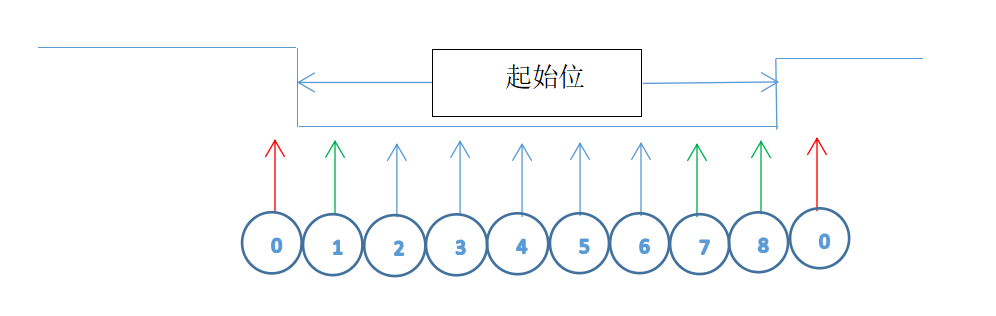
图1
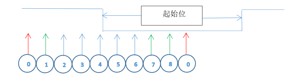
图2
1.判多的方式依然需要边沿检测配合
边沿检测可以正确定位数据的位置。如图1,由于0采样点为高电平,1采样点为低电平,可以知道在此处有下降沿变化。由此推断采样点1,2…8应该分布在整个数据为上。图2可以看出,如果不考虑边沿检测,从采样点1到8可能随机分布在不同的接收位上,极端的情况如图2,一半采样在IDLE位(高电平),一半在起始位,在这种情况下,判多方法也一样无法正确将接收的位提取出来。如图2,从第一个0采样点到到采样点8,统计为1的个数为5,0的个数为4,判定为1,此时没用捕获到起始位。如果从第2个0采样点开始,如果起始位后面的数据为1,9次采样后的结果也是1多0少,因此将会丢失起始位的判定,从而无法成功捕获整个数据帧。因此需要首先检测边沿,确定位起始后在进行判多处理。
除了边沿检测,是否还有其他的方法可以成功捕获起始位呢?可以使用滑动串口的方法,即在IDLE状态通过移位的方式动态统计8采用中1的个数,判定起始位。
2. 判决方法
如图1,一旦边沿确定后,利用采样点1…8的值就可以进行判决,判决方法如下:采样点1…8中1的个数大于等于5,判定该数据位为1,否则为0。
3. 其它接收位的判定
起始位正确定位后,紧随起始位的其它位(数据位、校验位、停止位等)不用判断边沿,直接从下一个的0采样点开始统计每个位的1的个数即可。
例1,利用判多设计RX的参数化接收程序,要求使用8次过采样。
`timescale 1ns / 1ps
module rx_more_one
#(
   parameter PARITY = "ODD",    //"ODD"--odd parity, "EVEN"--even parity, others--no parity
   parameter STOP_BIT = 1
)
(
   input sys_clk,
   input rst,

   input rx,

   input bd8_rate,

   output reg [7:0] rx_data = 0,
   output reg rx_rdy = 0
);


localparam [ 3: 0 ]
           IDLE0     = 0,
           IDLE1     = 1,
           START     = 2,
           FIRST_BIT = 3,
           SEC_BIT   = 4,
           THIRD_BIT = 5,
           FOUTH_BIT = 6,
           FIF_BIT   = 7,
           SIX_BIT   = 8,
           SEVN_BIT  = 9,
           EIGTH_BIT = 10,
           PAR_BIT   = 11,
           STOP1_BIT = 12,
           STOP2_BIT = 13;

localparam EXTRA_COUNT = (PARITY == "ODD"||PARITY == "EVEN") ? 8 : 0;
localparam EXTRA_STOP_COUNT = (STOP_BIT == 2) ? 8 : 0;


reg [ 1: 0 ] rx_r;
reg rx_nedge; //
reg [ 7: 0 ] rx_data_tmp;
reg rx_rdy_tmp;
reg [ 7: 0 ] sample_bit;

wire [ 3: 0 ] count_one;
wire rx_bit;


reg [ 3: 0 ] sample_st_cs, sample_st_ns;
reg [ 6: 0 ] sample_count_cs, sample_count_ns;
reg [ 6: 0 ] sample_count_cs_r;


assign count_one = sample_bit[ 0 ] + sample_bit[ 1 ] + sample_bit[ 2 ] + sample_bit[ 3 ] + sample_bit[ 4 ] + sample_bit[ 5 ] + sample_bit[ 6 ] + sample_bit[ 7 ];

assign rx_bit = ( count_one > 4 ) ? 1'b1 : 1'b0;

always@( posedge sys_clk or posedge rst )
if ( rst )
begin
    rx_r <= 0;
    rx_nedge <= 0;
end
else
begin
    if ( bd8_rate )
    begin
        rx_r <= { rx_r[ 0 ], rx };         // rx shift left
        rx_nedge <= (rx_r == 2'b10) ? 1'b1 : 1'b0;  // capture the falling edge
    end
end


always@( posedge sys_clk or posedge rst )
if ( rst )
begin
    sample_st_cs <= IDLE0;
end
else
begin
    sample_st_cs <= sample_st_ns;
end


always@( posedge sys_clk or posedge rst )
if ( rst )
begin
    sample_count_cs <= 0;
end
else
begin
    sample_count_cs <= sample_count_ns;
end


always@( * )
begin
    sample_count_ns = sample_count_cs;
    sample_st_ns = sample_st_cs;

    if ( bd8_rate )
    begin
        case ( sample_st_cs )
        IDLE0:
        begin     //idle state, waiting for ta least 10bits 1
            if ( sample_count_cs == (80 + EXTRA_COUNT + EXTRA_STOP_COUNT ) )
                sample_st_ns = IDLE1;
            else if ( rx_r[ 1 ] )
                sample_count_ns = sample_count_cs + 1;
            else
                sample_count_ns = 0;
        end
        IDLE1:
        begin //waiting for start_bit's edge
            sample_count_ns = 0;
            if ( rx_nedge )
                sample_st_ns = START;
        end
        START:
        begin
            sample_count_ns = sample_count_cs + 1;
            if ( sample_count_cs == 5 )
            begin
                sample_count_ns = 0;
                if ( rx_bit ) // sample times bigger than 4
                    sample_st_ns = IDLE1; // detect start flag
                else
                    sample_st_ns = FIRST_BIT;
            end
        end
        FIRST_BIT:
        begin
            sample_count_ns = sample_count_cs + 1;

            if ( sample_count_cs == 7 )
            begin
                sample_count_ns = 0;
                sample_st_ns = SEC_BIT;
            end
        end
        SEC_BIT:
        begin
            sample_count_ns = sample_count_cs + 1;

            if ( sample_count_cs == 7 )
            begin
                sample_count_ns = 0;
                sample_st_ns = THIRD_BIT;
            end
        end
        THIRD_BIT:
        begin
            sample_count_ns = sample_count_cs + 1;

            if ( sample_count_cs == 7 )
            begin
                sample_count_ns = 0;
                sample_st_ns = FOUTH_BIT;
            end
        end
        FOUTH_BIT:
        begin
            sample_count_ns = sample_count_cs + 1;

            if ( sample_count_cs == 7 )
            begin
                sample_count_ns = 0;
                sample_st_ns = FIF_BIT ;
            end
        end
        FIF_BIT:
        begin
            sample_count_ns = sample_count_cs + 1;

            if ( sample_count_cs == 7 )
            begin
                sample_count_ns = 0;
                sample_st_ns = SIX_BIT;
            end
        end
        SIX_BIT:
        begin
            sample_count_ns = sample_count_cs + 1;

            if ( sample_count_cs == 7 )
            begin
                sample_count_ns = 0;
                sample_st_ns = SEVN_BIT;
            end
        end
        SEVN_BIT:
        begin
            sample_count_ns = sample_count_cs + 1;

            if ( sample_count_cs == 7 )
            begin
                sample_count_ns = 0;
                sample_st_ns = EIGTH_BIT;
            end
        end
        EIGTH_BIT:
        begin
            sample_count_ns = sample_count_cs + 1;

            if ( sample_count_cs == 7 )
            begin
                sample_count_ns = 0;

                if ( ( PARITY == "ODD" ) || ( PARITY == "EVEN" ) )
                    sample_st_ns = PAR_BIT;
                else
                    sample_st_ns = STOP1_BIT;
            end
        end
        PAR_BIT:
        begin
            sample_count_ns = sample_count_cs + 1;

            if ( sample_count_cs == 7 )
            begin
                sample_count_ns = 0;
                sample_st_ns = STOP1_BIT;
            end
        end
        STOP1_BIT:
        begin
            sample_count_ns = sample_count_cs + 1;

            if ( sample_count_cs == 6 )
            begin
                sample_count_ns = 0;

                if ( STOP_BIT == 2 )
                    sample_st_ns = STOP2_BIT;
                else
                    sample_st_ns = IDLE1;
            end
        end
        STOP2_BIT:
        begin
            sample_count_ns = sample_count_cs + 1;

            if ( sample_count_cs == 7 )
            begin
                sample_count_ns = 0;
                sample_st_ns = IDLE1;
            end
        end
        endcase
    end
end


always@( posedge sys_clk or posedge rst )
if ( rst )
begin
    sample_bit <= 0;
    rx_rdy_tmp <= 1'b0;
    rx_data_tmp <= 0;
end
else
begin
    rx_rdy_tmp <= 1'b0;

    if ( sample_st_cs == IDLE1 )
        sample_bit <= rx_r[ 1 ];

    case ( sample_st_cs )
    START, FIRST_BIT, SEC_BIT, THIRD_BIT, FOUTH_BIT, FIF_BIT, SIX_BIT, SEVN_BIT, EIGTH_BIT, PAR_BIT, STOP1_BIT, STOP2_BIT :
    begin
        if ( bd8_rate )
            sample_bit <= { sample_bit[ 6: 0 ], rx_r[ 1 ] };
    end
    endcase

    sample_count_cs_r <= sample_count_cs;

    if (( sample_count_cs_r == 7 ) & bd8_rate )
    begin //delay one clock
        case ( sample_st_cs )
        FIRST_BIT:  rx_data_tmp[ 0 ] <= rx_bit;
        SEC_BIT:    rx_data_tmp[ 1 ] <= rx_bit;
        THIRD_BIT:  rx_data_tmp[ 2 ] <= rx_bit;
        FOUTH_BIT:  rx_data_tmp[ 3 ] <= rx_bit;
        FIF_BIT:    rx_data_tmp[ 4 ] <= rx_bit;
        SIX_BIT:    rx_data_tmp[ 5 ] <= rx_bit;
        SEVN_BIT:   rx_data_tmp[ 6 ] <= rx_bit;
        EIGTH_BIT:
        begin
            rx_data_tmp[ 7 ] <= rx_bit;
            rx_rdy_tmp <= 1'b1;
        end
        default: ;
        endcase
    end
end


always@( posedge sys_clk )
begin
    if ( rx_rdy_tmp )
    begin
        rx_data <= rx_data_tmp;
        rx_rdy <= 1'b1;
    end
    else rx_rdy <= 1'b0;
end

endmodule
仿真程序:仿真程序继续使用上节内容提供的(中心对齐)testbench,
`timescale 1 ns / 1 ps

module tb
(
);


parameter BAUD_RATE = 115200;
parameter FREQUENCY = 100_000_000;

localparam  TX_DIV_COE = FREQUENCY / (BAUD_RATE);
localparam  RX_DIV_COE = FREQUENCY / (BAUD_RATE*8);

reg [18:0]  tx_clk_div;
reg [18:0]  rx_clk_div;

parameter PERIOD = 10   ; //100Mhz

reg   clk;
reg   rst;
reg   rx_bd_en;
reg   tx_bd_en;


initial
begin
    clk = 0;
    #(PERIOD/2);

    forever
        #(PERIOD/2) clk = ~clk;
end

initial
begin
    rst = 1;
    #50

    rst = 0;

     #300000;

//	 $stop;
end
wire   tx;
reg   [7:0] tx_count;
reg   [7:0] tx_data = 0;
reg   [9:0] tx_send=10'b11_1111_1111;


always@(posedge clk or posedge rst)
if(rst)
begin
    tx_count = 0;
end
else
begin
    if(tx_bd_en)
    begin
        if(tx_count == 50)
        begin
               tx_data <= tx_data + 1;
                tx_send<= {1'b1, tx_data, 1'b0};
            tx_count = 0;
        end
        else
        begin
               tx_send<= {1'b1, tx_send[8:1]};
            tx_count = tx_count + 1;
        end
    end
end

assign tx = tx_send[0];

always@(posedge clk or posedge rst)
if(rst)
begin
    tx_clk_div <= 0;
    rx_clk_div <= 0;
    tx_bd_en <= 0;
    rx_bd_en <= 0;
end
else
begin
    tx_bd_en <= 1'b0;
    if(tx_clk_div == TX_DIV_COE)
    begin
        tx_clk_div <= 0;
        tx_bd_en <= 1'b1;
    end
    else
        tx_clk_div <= tx_clk_div + 1'b1;

    rx_bd_en <= 0;
    if(rx_clk_div == RX_DIV_COE)
    begin
        rx_clk_div <= 0;
        rx_bd_en <= 1'b1;
    end
    else
        rx_clk_div <= rx_clk_div + 1;
end


wire  [7:0] rx_data;
wire  rx_rdy;

//rx #(.PARITY ("NONE"))
rx_more_one #
(
    .PARITY ("NONE"),
    .STOP_BIT (1)
)
rx_inst
(
    .sys_clk    (clk),
    .rst        (rst),
    .rx         (tx),
    .bd8_rate   (rx_bd_en),
    .rx_data    (rx_data),
    .rx_rdy     (rx_rdy)
);


endmodule
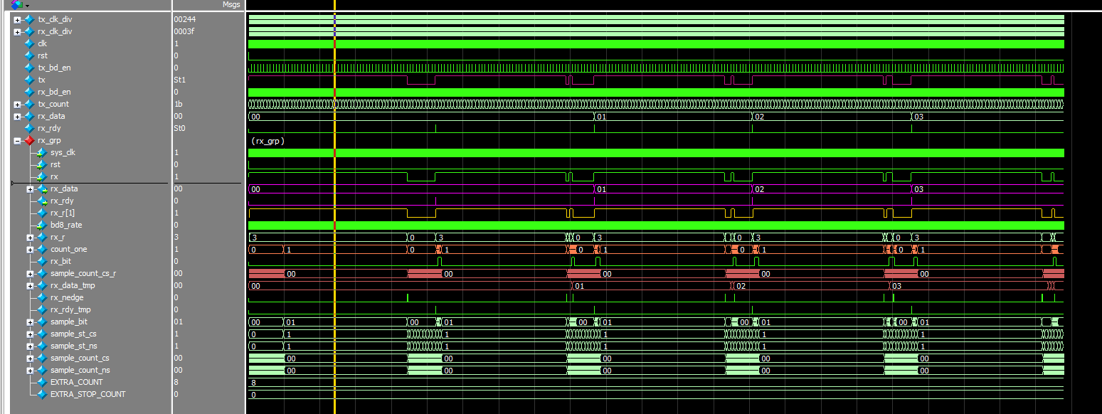
图3-1
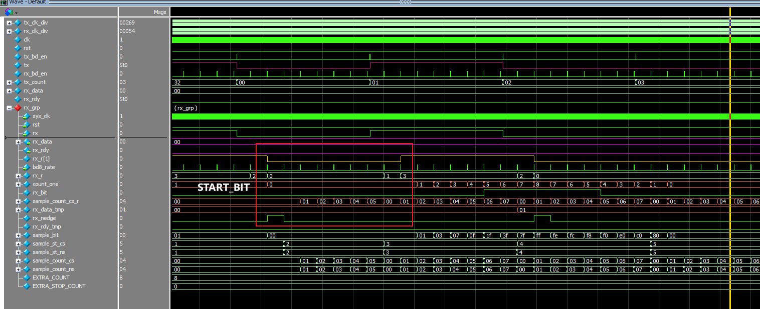
图3-2
由于判多相对于中心对齐的采样相对复杂,因此例1对判多的描述采用了3段式状态机实现,第一段采用实现次态(sample_st_ns)到现态(sample_st_cs)的转换。第二段描述了次态逻辑,根据sample_count_cs的值实现状态跳转。第三段描述了rx的数据采样及实现。

老师,代码里面好像写错了一个,assign count_one = sample_bit [0] +……sample_bit [6] + sample_bit [7] 文件里面 将第7位写成了第0位。
有一个疑惑:
代码的最后用了一个时序逻辑,将rx_data_tmp 寄存到rx_data里面,将rx_rdy_tmp寄存到rx_rdy里面 输出,而不是直接输出rx_data_tmp和rx_rdy_tmp,是为了保证输出信号的稳定么?
1. 谢谢你的回复,已经改正!
2. 你理解的是正确的。