在网络综合设计中,IP层发送模块中将数据写入MAC层发送的FIFO中。MAC层发送模块需要将payload数据打成完整的以太网数据包后,以8-bit的数据形式伴随着数据使能,根据PHY层的网速发给PHY。本文将实现MAC发送模块。
1.MAC层发送需要实现的任务
MAC层发送模块需要完成的任务如下:
- 从18 in/9 out FIFO中读出IP层传递过来的数据包(判断是否需要加上Padding)
- 加上CRC校检
- 将处理过的数据传递进8/8的乒乓buffer,为之后的数据处理提供更高的效率
- 加上前导字(preamble),以及在数据包和数据包之间的GAP,将数据包按照检测出的网速(MII和RGMII/GMII分开)发送给PHY层
2.MAC层发送部分的框图结构
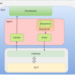
图1所示为网络综合实验框图,其中红框部分是MAC层的发送(eth_mac_tx.v)。
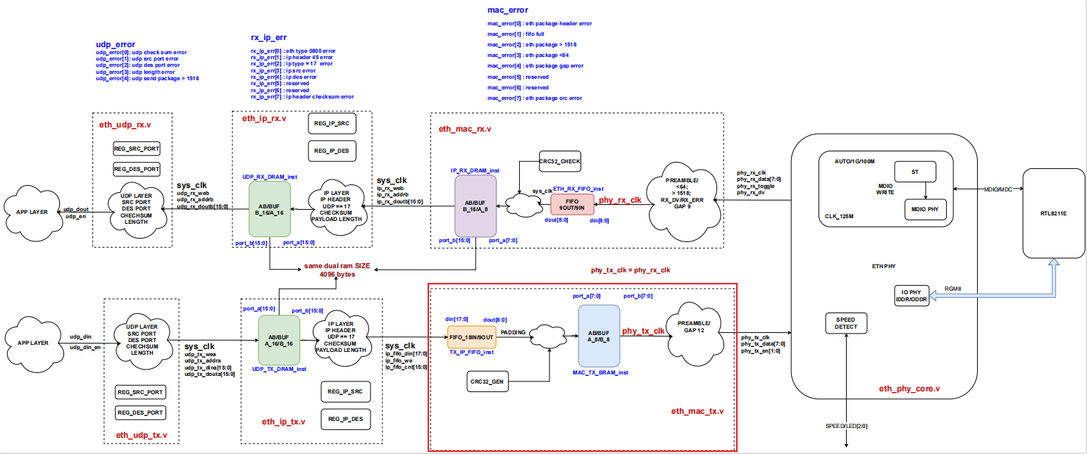
图1 网络综合实验框图
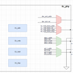
图2所示为MAC层的发送(eth_mac_tx.v)。
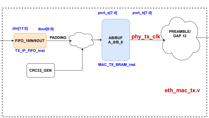
图2 eth_mac_tx.v
3.MAC层发送设计
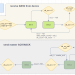
MAC层发送的代码中主要有tx_ip_fifo_st和mac_tx_st两个状态机。tx_ip_fifo_st读从IP层发送过来的FIFO数据(判断是否需要加上padding),并将其加上CRC后,写入A/B Buffer。mac_tx_st读出A/B Buffer里的数据,根据MII的类型(MII/RGMII等)分开发送前导字和数据,最后加上数据包之间的gap。之所以需要分开MII的类型发送前导字和数据,是因为在一个时钟下MII无法发送1个字节,而RGMII可以在一个时钟下发送1个字节。
tx_ip_fifo_st:
图3所示为tx_ip_fifo_st状态机的简易流程图(注意省略了状态转移条件不满足时,停留在当前状态的箭头)。
- 状态0和状态1指定了读A/B Buffer的地址,因为A/B Buffer是双端口RAM,需要等待两个时钟周期才能成功读出数据
- 状态2判断读出的标志,指示当前A/B Buffer是否可写
- 状态3和状态4将FIFO中存储的数据长度读出来
- 状态5将FIFO中的数据读出,写入A/B Buffer
- 状态6可根据上层接口调整(这里也可以省略)
- 状态7检查不加CRC的数据包长度是否大于60,如果数据包长度小于60,填充数据0,直到数据包长度达到60
- 状态8,状态9,状态10,状态11在数据包末尾加上CRC
- 状态12和13将数据总长度,A/B Buffer可读的标志写进A/B Buffer
- 状态14和状态15转到A/B Buffer另一侧,重新准备写入数据
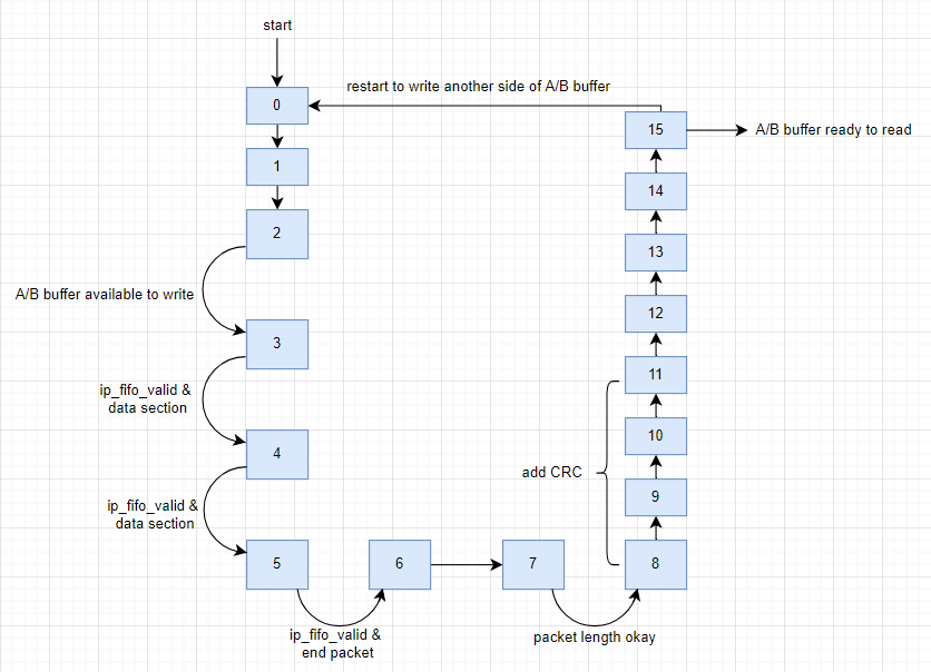
图3 tx_ip_fifo_st流程图
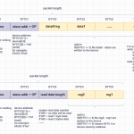
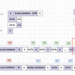
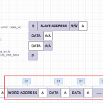
因为FIFO是18 in/9 out,Xilinx FIFO IP不等宽的端口读写数据的顺序如图4和图5所示:
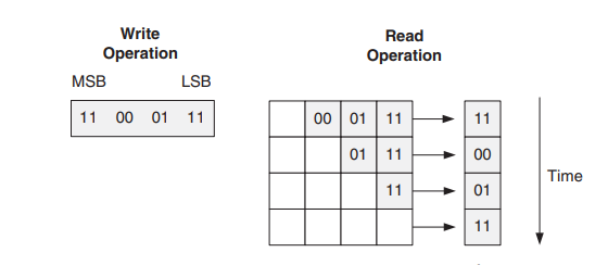
图4
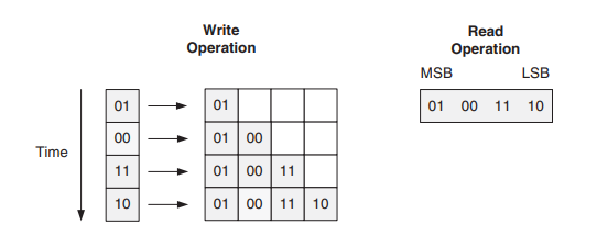
图5
4.MAC层发送Verilog代码
MAC层发送,eth_mac_tx.v的代码如下(这里省略了CRC32生成代码,详情见文章互联网MAC层CRC32 生成器):
`timescale 1ns / 1ps


module eth_mac_tx #
(
    parameter MAC_TX_IFG     = 12,   //inter-frame gap
    parameter MAC_TX_CRC_EN  = 1,

    parameter MAC_TXBUF_SIZE = 11,
    parameter MAC_TXIDX_BIT  = 1
)
(
    input  sys_clk,

    input  [17:0] ip_fifo_din,
    input  ip_fifo_we,
    output [15:0] ip_fifo_cnt,

    input  mac_tx_clk,
    output reg [7:0] mac_tx_data = 0,
    output reg [1:0] mac_tx_en = 0,

    input  [2:0] eth_speed,
    input  reset
);
//=============== FIFO related signals ===============================
wire [8:0] ip_fifo_dout;
wire ip_fifo_valid;
reg  ip_fifo_rd = 0;
wire ip_fifo_full;
wire ip_fifo_empty;
TX_IP_FIFO   TX_IP_FIFO_inst
(
    .wr_clk (sys_clk),              // input wire wr_clk
    .din    (ip_fifo_din),          // input wire [17 : 0] din
    .wr_en  (ip_fifo_we),           // input wire wr_en
    .full   (ip_fifo_full),         // output wire full

    .rd_clk (sys_clk),              // input wire rd_clk
    .rd_en  (ip_fifo_rd),           // input wire rd_en
    .dout   (ip_fifo_dout),         // output wire [8 : 0] dout
    .empty  (ip_fifo_empty),        // output wire empty

    .valid  (ip_fifo_valid),        // output wire valid
    .wr_data_count(ip_fifo_cnt),    // output wire [10 : 0] wr_data_count

    .rst    (reset)                 // input wire rst
);
//=========================================================================
reg  ip_tx_wea = 0;
wire [MAC_TXBUF_SIZE + MAC_TXIDX_BIT - 1:0] ip_tx_addra;
reg  [7:0] ip_tx_dina;
wire [7:0] ip_tx_douta;

reg  [MAC_TXBUF_SIZE - 1:0] ip_tx_addra_sub = 0;
reg  [MAC_TXIDX_BIT - 1:0] ip_tx_ida = 0;
assign ip_tx_addra = {ip_tx_ida, ip_tx_addra_sub};
//=========================================================================
reg crc_init = 0;
reg crc_rd = 0;
reg crc_wr = 0;   //date enable
wire [7:0] crc_out;     //CRC result
wire crc_end;
reg [15:0] fifo_cnt = 0;
reg [15:0] fifo_len = 0;
reg [3:0] tx_ip_fifo_st = 0;
always @ (posedge sys_clk)
if(reset)
begin
    ip_tx_wea <= 0;
    ip_tx_ida <= 0;
    ip_fifo_rd <= 0;
    tx_ip_fifo_st <= 0;
end
else case(tx_ip_fifo_st)
0:
begin
    crc_init <= 1;      //initialize the CRC
    crc_rd <= 0;
    crc_wr <= 0;
    fifo_cnt <= 0;
    fifo_len <= 0;

    ip_tx_addra_sub <= {MAC_TXBUF_SIZE{1'b1}};          //addr 2047
    ip_tx_wea <= 0;
    ip_fifo_rd <= 0;

    tx_ip_fifo_st <= 1;
end
1:
begin
    crc_init <= 0;
    ip_tx_addra_sub <= {MAC_TXBUF_SIZE{1'b1}};          //addr 2047
    tx_ip_fifo_st <= 2;
end
2:    //read from A/B Buffer, for address 2047, read after 2 clocks
begin
    if(ip_tx_douta[7] == 0)     //indicates A/B buffer is available to write
    begin
        ip_fifo_rd <= 1;        //read data from FIFO
        tx_ip_fifo_st <= 3;
    end
end
3:
begin
    if(ip_fifo_valid)
    begin
        if(ip_fifo_dout[8] == 0)      // normal data
        begin
            fifo_len[15:8] <= ip_fifo_dout[7:0];     //read packet length upper 8 bits from FIFO, big-endian
            tx_ip_fifo_st <= 4;
        end
    end
end
4:
begin
    if(ip_fifo_valid)
    begin
        if(ip_fifo_dout[8] == 0)     // normal data
        begin
            fifo_len[7:0] <= ip_fifo_dout[7:0];     //read packet length lower 8 bits from FIFO
            tx_ip_fifo_st <= 5;
        end
    end
end
5:
begin
    ip_tx_wea <= 0;
    crc_wr <= 0;
    if(ip_fifo_valid)
    begin
        ip_tx_dina <= ip_fifo_dout[7:0]; //write into buffer, and calculate CRC

        if(ip_fifo_dout[8])      //end packet segment
        begin
            ip_tx_wea <= 0;
            crc_wr <= 0;
            ip_fifo_rd <= 0;
            tx_ip_fifo_st <= 6;
        end
        else
        begin
            if(fifo_len == fifo_cnt)     // finished reading current packet
            begin
                ip_tx_wea <= 0;
                crc_wr <= 0;
            end
            else          //write into A/B Buffer
            begin
                ip_tx_addra_sub <= ip_tx_addra_sub + 1;      //move up the address
                fifo_cnt <= fifo_cnt + 1;        //count data read from FIFO
                ip_tx_wea <= 1;
                crc_wr <= 1;
            end
        end
    end
end
6:
begin
    tx_ip_fifo_st <= 7;
end
7:
begin
    if(fifo_cnt < 60)         //if packet length(excluding CRC) < 60
    begin                     // padding with 0
        fifo_cnt <= fifo_cnt + 1;
        ip_tx_addra_sub <= ip_tx_addra_sub + 1;
        ip_tx_dina <= 0;       //data 0
        ip_tx_wea <= 1;
        crc_wr <= 1;
    end
    else     //packet length okay
    begin
        ip_tx_wea <= 0;
        crc_wr <= 0;
        crc_rd <= 1;      //enable CRC
        tx_ip_fifo_st <= 8;
    end
end
8:     //state 8 - 11, fill 4 bytes CRC
begin
    fifo_cnt <= fifo_cnt + 1;
    ip_tx_addra_sub <= ip_tx_addra_sub + 1;
    ip_tx_dina <= crc_out;       // fill CRC
    ip_tx_wea <= 1;

    tx_ip_fifo_st <= 9;
end
9:
begin
    fifo_cnt <= fifo_cnt + 1;
    ip_tx_addra_sub <= ip_tx_addra_sub + 1;
    ip_tx_dina <= crc_out;      // fill CRC
    ip_tx_wea <= 1;

    tx_ip_fifo_st <= 10;
end
10:
begin
    fifo_cnt <= fifo_cnt + 1;
    ip_tx_addra_sub <= ip_tx_addra_sub + 1;
    ip_tx_dina <= crc_out;      // fill CRC
    ip_tx_wea <= 1;

    tx_ip_fifo_st <= 11;
end
11:
begin
    fifo_cnt <= fifo_cnt + 1;
    ip_tx_addra_sub <= ip_tx_addra_sub + 1;
    ip_tx_dina <= crc_out;      // fill CRC
    ip_tx_wea <= 1;

    crc_rd <= 0;            //disable CRC
    tx_ip_fifo_st <= 12;
end
12:
begin
    ip_tx_addra_sub <= {{(MAC_TXBUF_SIZE- 1){1'b1}}, 1'b0};      //addr 2046 {10'b1,1'b0}
    ip_tx_dina <= fifo_cnt[7:0];                  //packet size

    ip_tx_wea <= 1;
    tx_ip_fifo_st <= 13;
end
13:
begin
    ip_tx_addra_sub <= {MAC_TXBUF_SIZE{1'b1}};      // addr 2047
    ip_tx_dina <= {4'b1000, fifo_cnt[11:8]};        //flag and the packet size following bit

    ip_tx_wea <= 1;
    tx_ip_fifo_st <= 14;
end
14:
begin
    ip_tx_addra_sub <= {MAC_TXBUF_SIZE{1'b1}};          //addr 2047

    ip_tx_wea <= 0;
    tx_ip_fifo_st <= 15;
end
15:
begin
    ip_tx_addra_sub <= {MAC_TXBUF_SIZE{1'b1}};          //addr 2047
    ip_tx_wea <= 0;
    ip_tx_ida <= ip_tx_ida + 1;         //proceed to next buffer

    tx_ip_fifo_st <= 0;
end
default:     tx_ip_fifo_st <= 0;
endcase
//======================== CRC related signals ===========================
CRC_gen  CRC_gen_inst
(
    .clk        (sys_clk),
    .init       (crc_init),
    .frame_data (ip_tx_dina),
    .data_en    (crc_wr),
    .crc_rd     (crc_rd),

    .crc_out    (crc_out),
    .crc_end    (crc_end),

    .rst        (reset)
);
//===================== A/B Buffer related signals ====================

reg  ip_tx_web = 0;
wire [7:0] ip_tx_doutb;

reg  [MAC_TXBUF_SIZE - 1:0] ip_tx_addrb_sub = 0;
reg  [MAC_TXIDX_BIT - 1:0] ip_tx_idb = 0;
wire [MAC_TXBUF_SIZE + MAC_TXIDX_BIT - 1:0] ip_tx_addrb = {ip_tx_idb, ip_tx_addrb_sub};
//============================ A/B Buffer =============================
MAC_TX_BRAM   MAC_TX_BRAM_inst
(
    .clka   (sys_clk),      // input wire clka
    .wea    (ip_tx_wea),    // input wire [0 : 0] wea
    .addra  (ip_tx_addra),  // input wire [11 : 0] addra
    .dina   (ip_tx_dina),   // input wire [7 : 0] dina
    .douta  (ip_tx_douta),  // output wire [7 : 0] douta

    .clkb   (mac_tx_clk),   // input wire clkb
    .web    (ip_tx_web),    // input wire [0 : 0] web
    .addrb  (ip_tx_addrb),  // input wire [11 : 0] addrb
    .dinb   (0),            // input wire [7 : 0] dinb
    .doutb  (ip_tx_doutb)   // output wire [7 : 0] doutb
);
//=======================================================================
//decide MII or RGMII
reg eth_nibble = 0;
always @ (posedge mac_tx_clk or posedge reset)
if(reset)
begin
    eth_nibble <= 0;
end
else
begin
    if(eth_speed == 1 || eth_speed == 3) // 2.5m, 25m MII
        eth_nibble <= 1;
    else // RGMII or GMII
        eth_nibble <= 0;
end
//=========== prepare the preamble register ==================
reg [7:0] eth_preamble [0:7];
initial
begin
    eth_preamble [0] = 8'h55;
    eth_preamble [1] = 8'h55;
    eth_preamble [2] = 8'h55;
    eth_preamble [3] = 8'h55;
    eth_preamble [4] = 8'h55;
    eth_preamble [5] = 8'h55;
    eth_preamble [6] = 8'h55;
    eth_preamble [7] = 8'hd5;
end

//===============================================================

reg  [15:0] mac_tx_len = 0;
reg  [15:0] mac_tx_cnt = 0;
(* mark_debug = "true" *)reg  [3:0] mac_tx_st = 0;
always @ (posedge mac_tx_clk or posedge reset)
if(reset)
begin
    mac_tx_en <= 0;
    ip_tx_idb <= 0;
    ip_tx_web <= 0;
    mac_tx_st <= 0;
end
else case (mac_tx_st)
0:
begin
    mac_tx_en <= 0;
    mac_tx_cnt <= 0;
    ip_tx_web <= 0;
    ip_tx_addrb_sub <= {MAC_TXBUF_SIZE{1'b1}};      // addr 2047

    mac_tx_st <= 1;
end
1:
begin
    ip_tx_addrb_sub <= {MAC_TXBUF_SIZE{1'b1}};      // addr 2047
    mac_tx_st <= 2;
end
2:     //read from A/B Buffer, for address 2047, read after 2 clocks
begin
    if(ip_tx_doutb[7] == 1)   //indicates A/B buffer is available to read
    begin
        ip_tx_addrb_sub <= {{(MAC_TXBUF_SIZE - 1){1'b1}}, 1'b0};    //addr 2046 {10'b1,1'b0}
        mac_tx_st <= 3;
    end
end
3:
begin
    mac_tx_len[15:8] <= {4'b0000, ip_tx_doutb[3:0]};          //read packet length upper bits from A/B Buffer
    mac_tx_st <= 4;
end
4:
begin
    mac_tx_len[7:0] <= ip_tx_doutb;          //read packet length lower bits from A/B Buffer
    ip_tx_addrb_sub <= 0;

    if(eth_nibble)     //MII
        mac_tx_st <= 5;
    else               //RGMII or GMII
        mac_tx_st <= 9;
end

// MII transmit
5: // state 5 - 6 MII transmit preamble
begin
    mac_tx_cnt <= mac_tx_cnt + 1;
    mac_tx_data <= eth_preamble[mac_tx_cnt];
    mac_tx_en <= 2'b11;
    mac_tx_st <= 6;
end
6: // state 5 - 6 MII transmit preamble
begin
    mac_tx_en <= 2'b10;

    if(mac_tx_cnt == 8)    //finished sending preamble
    begin
        mac_tx_cnt <= 0;
        mac_tx_st <= 7;
    end
    else
        mac_tx_st <= 5;
end
7: // state 7 - 8 MII transmit data
begin
    mac_tx_cnt <= mac_tx_cnt + 1;
    ip_tx_addrb_sub <= ip_tx_addrb_sub + 1;
    mac_tx_data <= ip_tx_doutb;
    mac_tx_en <= 2'b11;
    mac_tx_st <= 8;
end
8: // state 7 - 8 MII transmit data
begin
    mac_tx_en <= 2'b10;

    if(mac_tx_cnt == mac_tx_len)    //finished sending data
    begin
        mac_tx_cnt <= 1;
        mac_tx_st <= 11;
    end
    else mac_tx_st <= 7;
end

// RGMII transmit
9: // RGMII transmit preamble
begin
    mac_tx_en <= 2'b11;
    if(mac_tx_cnt == 6)
    begin
        mac_tx_data <= eth_preamble[7];      //finished sending preamble
        mac_tx_cnt <= 0;

        ip_tx_addrb_sub <= ip_tx_addrb_sub + 1;
        mac_tx_st <= 10;
    end
    else      //keep sending following preamble
    begin
        mac_tx_data <= eth_preamble[mac_tx_cnt];
        mac_tx_cnt <= mac_tx_cnt + 1;
    end
end

10: //RGMII transmit data
begin
    if(mac_tx_cnt == mac_tx_len)       //finished sending data
    begin
        mac_tx_cnt <= 1;
        mac_tx_en <= 0;
        mac_tx_st <= 11;
    end
    else
    begin
        mac_tx_cnt <= mac_tx_cnt + 1;
        ip_tx_addrb_sub <= ip_tx_addrb_sub + 1;
        mac_tx_data <= ip_tx_doutb;
        mac_tx_en <= 2'b11;
    end
end
11:    //gap 12 clock
begin
    mac_tx_en <= 0;
    mac_tx_cnt <= mac_tx_cnt + 1;

    ip_tx_addrb_sub <= {MAC_TXBUF_SIZE{1'b1}};    //addr 2047
    ip_tx_web <= 1;

    mac_tx_st <= 12;
end
12:
begin
    mac_tx_cnt <= mac_tx_cnt + 1;

    ip_tx_addrb_sub <= {MAC_TXBUF_SIZE{1'b1}};    //addr 2047
    ip_tx_web <= 0;

    if(mac_tx_cnt == (MAC_TX_IFG << nibble) )    // packet gap
    begin
        ip_tx_idb <= ip_tx_idb + 1;
        mac_tx_st <= 0;
    end
end

default: mac_tx_st <= 0;
endcase

//=======================================================================

endmodule
mac_tx_st:
图6所示为mac_tx_st状态机的简易流程图(注意省略了状态转移条件不满足时,停留在当前状态的箭头)。
- 状态0和状态1指定了读A/B Buffer的地址,因为A/B Buffer是双端口RAM,需要等待两个时钟周期才能成功读出数据
- 状态2判断读出的标志,指示当前A/B Buffer是否可读
- 状态3和状态4将A/B Buffer中存储的数据长度读出来,并且状态4将MII和RGMII/GMII分开
- 状态5和状态6发送MII的前导字
- 状态7和状态8发送MII的数据
- 状态9发送RGMII/GMII的前导字
- 状态10发送RGMII/GMII的数据
- 状态11和状态12发送数据包之间的gap
- 状态12转到A/B Buffer另一侧,重新准备读数据
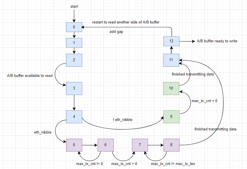
图6 mac_tx_st流程图
关于模块的详细解释请参见对应的视频。