在时序约束中,对于input delay的约束也至关重要,该模型主要对外部数据的输入在FPGA内部对于时钟边沿的延迟约束,以确保输入数据在FPGA内部使用时能满足建立时间和保持时间,当时钟边沿来临时能正确采样输入数据。如果是PCB板上的两个FPGA之间数据交换,还应该对输出数据的FPGA进行output_delay的约束,以做到在整个数据传递的路径中设置正确的延时约束,使系统能稳定可靠工作。关于output_delay的设置将在后续文章种介绍。设置input_delay的命令为set_input_delay, 可以在SDC或XDC下设用,也可以在TCL命令下使用。
1. Input delay模型和应用场景
在FPGA程序设计中,有各种各样应用场景会与输入延迟相关,常见的应用场景有如下几种。
- 确定的外部延迟
如果外部延迟是一个确定的值,在FPGA输入延时约束时可以做到较为精确的设置。这种应用场景往往源时钟点,源数据点已经确定,源数据点与源时间点的相位关系已经确定。PCB板布线已经完成,数据的外部延时已经确定,此时到达FPGA的时钟输入点和数据的数据输入点的延迟关系(差值)可以精确计算出来,因此可以使用set_input_delay根据计算值进行约束。时钟与数据的布线关系如图1所示。
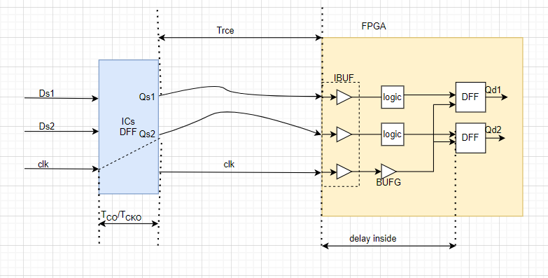
图1
对于确定的延时,在设定输入延时时可以将max, min 设置成同样的值,如Tco=0.1 ns, Trce=0.6 ns, 总的延时为Tdelay=Tco+Trce=0.7 ns, 输入延时可以用如下语句设置:
set_input_delay -clock [get_clocks {clk}] -0.700 [get_ports {din} ] (1)
其中din是Verilog顶层文件的输入端口,在硬件板卡上分别与Qs1或Qs2相连的端口。
- 不确定的外部延迟
更多的时候外部延迟不确定,或不能完全确定,此时在使用set_input_delay时可以给定一个范围,一般用mix 和min限定。其中 max对应setup time , min对应hold time。外部延迟不能确定或不能完全确定,主要原因有如下几种,
(1)PCB布线时,由于时钟或数据线穿透PCB多层,而每层的介电常数可能不同(主要影响电磁波的传输速度),当然使用好的EDA工具可做出较为精确的估计。
(2)对于总线约束时,总线内的各个分线可能做不到完全等长。
(3)数据线的起点(源)到数据输入点(FPGA的输入管脚)之间有其它组合逻辑。当然时钟线也可能有驱动器件等。
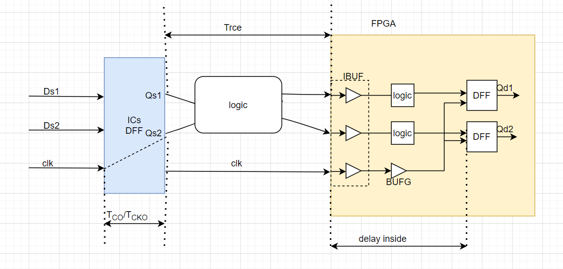
图2
对于不能确定,或者不能准确给出固定延迟量的设定一般会给出一个范围。如图3所示。
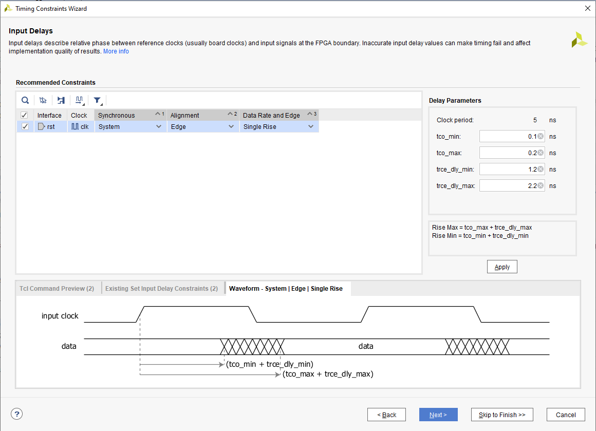
图3
对于延迟不能完全确定的延迟模型,可以用如下两条语句设定。其中时间单位为 ns , 时间值可正可负,根据实际硬件电路的延迟确定。
set_input_delay -clock [get_clocks *] -min 0.200 [get_ports { { din[ 0 ] }, { din[ 1 ] } }] (2)
set_input_delay -clock [get_clocks *] -max 1.200 [get_ports{ {din [ 0 ] }, { din[ 1 ] } } ] (3)
如果系统只有一个确定的时钟(create_clock),可以使用get_clocks*, 一般情况下应明确指出数据对应的是哪个时钟。
为什么说 -min是对hold time 的约束,-max是对setup time的约束呢?
假设时钟周期为5 ns ,从图3的示意图可以看出,-min是指当时钟沿来后,数据data相对于时钟input clock的延迟,如果该延迟不满足hold time delay, Vivado布线工具可以调整FPGA的时钟与数据之间的延时,以达到hold time 的约束条件。-max 是最大延迟,假设3ns , 时钟周期为5 ns, 因此setup time 的空间为5 ns-3ns =2 ns , 因此布线工具就会调整FPGA内的时钟与数据之间的延时关系以满足setup time 的需求。对于FPGA器件一般setup time 时间,不同的FPGA器件内部的寄存器的setup time不同,但是范围约在为0.2-0.6 ns之间。假设setup time 为0.6ns, 则FPGA内部的数据相对于时钟的延迟余量只有2ns-0.6ns=1.4ns。因此布线工具应在满足此要求下进行布线,如合理选择寄存器的位置,增加或减小布线资源等。最终EDA布线工具根据布线结果计算线路的各个延迟,并给出详尽的报告。
2. Input delay的语法
Input delay约束设计命令,语法格式及参数,该语法格式适用于SDC,XDC文件,下面将这部分内容一种英文对照的方式
- Input delay的命令:set_input_delay
Description: 描述
Set input delay on ports: 设置端口的延迟(delay)时间 ,
Syntax: 语法
set_input_delay [-clock <args>] [-reference_pin <args>] [-clock_fall] [-rise]
[-fall] [-max] [-min] [-add_delay] [-network_latency_included]
[-source_latency_included] [-quiet] [-verbose] <delay>
<objects>
各个参数的解释如表1
| Name (名称) | description | 描述 |
| [-clock] | Relative clock | 相关时钟或参考时钟 |
| [-reference_pin] | Relative pin or port | 相关或参看管脚(端口),主要这里端口是指顶层文件的端口。 |
| [-clock_fall] | Delay is relative to falling edge of clock | 给定的delay值是以时钟下降沿为参考的。 |
| [-rise] | Specifies rising delay | 指定上升沿delay约束 |
| [-fall] | Specifies falling delay | 指定下降沿delay约束 |
| [-max] | Specifies maximum delay | 指定最大延时约束 |
| [-min] | Specifies minimum delay | 指定最小延时约束 |
| [-add_delay] | Don’t remove existing input delay | 新加的约束与已有的约束共存,及不移出已经设定的输入延迟约束 |
| [-network_latency_included] | Specifies network latency of clock already included | |
| [-source_latency_included] | Specifies source latency of clock already included | |
| [-quiet] | Ignore command errors | 忽略命令错误 |
| [-verbose] | Suspend message limits during command | 命令执行时提供详尽的消息 |
| <delay> | Delay value | 延时数据 |
| <objects> | List of ports | 例举将要约束的端口 |
Description: 说明
(1)Note: The XDC > Timing Constraints language templates and the Timing Constraints Wizard in the Vivado IDE offer timing diagrams and additional details around defining specific timing constraints. You can refer to these sources for additional information.
阅读或使用XDC语言模板或使用Vivado IDE约束向导可以得到形象化的图表输入或编辑方式,并能获得更多细节, 向导设计的入口如图4,5 所示。
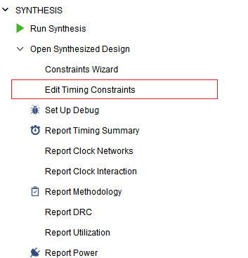
图4
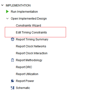
图5
Specifies the external system-level path delay on a primary input port relative to a clock edge at the interface of the design. The input delay value is specified in nanoseconds (ns), and can be positive or negative, depending on the clock and data relative phase at the interface of the device.
指定FPGA外部数据相对于时钟边沿(上升沿或下降沿)的延时,以纳秒(ns)为单位,浮点数(float),可以为整数也可以为小数,可以是整数也可以为负数。
(2)Note: If the input port also has a set_max_delay constraint assigned, the specified input delay value is considered part of the max_delay computation. That is, the input delay consumes a portion of the max_delay on the timing path that includes the input port.
This command returns nothing if successful, or returns an error if it fails.
如果对输入端口同时有set_max_delay的约束,上面指定的输入延时将会变成Max_delay计算的一个部分。主意max_delay不同于 input_delay的max参数。如果布线后的延时不能满足要求将会返回错误信息(当然Vivado工具将尽最大努力,采用合理的布线算法尽可能的实现),布线后满足约束要求,该命令将不返回任何信息,但可以通过timing report 查看。有关set_max_delay的细节请参照
3. Input delay 参数说明
Arguments: 参数
(1)时钟参数
-clock <arg> – (Optional) Indicates that the input delay is relative to the specified clock. By default the rising edge is used. However the -clock_fall argument can be used to indicate that the falling edge should be used instead.
可选项,指出输入延迟与哪个时钟有关(通过create_clock 创建的时钟),缺省以时钟的上升沿作为参考。如果想用下降沿作为参考,可以使用 -clock_fall作为选项。
(2)时钟参考引脚
-reference_pin <arg> – (Optional) Specifies that the delay is relative to the active edge of a clock appearing on the specified pin or port rather than a clock.
可选项,可以直接指定管脚作为参考时钟,而不是使用已创建的时钟。(1),(2)应指定其中的一个。
(3)clock_fall
-clock_fall – (Optional) Specifies that the delay is relative to a falling edge of the clock rather than rising edge.
见(1)
(4)rise
-rise – (Optional) Specifies the input delay applies to rising transitions on the specified ports. The default is to apply the delay for both rising and falling transitions.
指定延时仅用于时钟上升沿部分,不用于下降沿部分。缺省的情况是双边沿。
(5)fall
-fall – (Optional) Specifies the input delay applied to falling transitions on the specified ports. The default is to apply the delay for both rising and falling transitions.
指定延时仅用于时钟下降沿部分,不用于上升沿部分。缺省的情况是双边沿,上升沿的约束参见(4)。
(6)max
-max – (Optional) Indicates the input delay specified is only used when calculating the maximum (longest) path delays.
-max 后面的数值仅指定最长的输入延迟,对于综合或布线setup time 的时序收敛提供参考。
(7)min
-min – (Optional) Indicates the input delay specified is only used when calculating the minimum (shortest) path delays.
-min 后面的数值仅指定最短的输入延迟,对于综合或布线hold time 的时序收敛提供参考。
(8)add_delay
-add_delay – (Optional) Add the specified delay constraint to the port, to coexist with any other set_input_delay constraints already defined on the port. The default behavior is to replace the existing delays.
-add_delay 是可选项,指定端口延时约束,与通过set_input_delay命令对该管脚的约束共存。缺省行为是对已约束的延时直接覆盖。
(9)network_latency_included
From Xilinx related description:
-network_latency_included – (Optional) Indicates that the clock network latency of the reference clock is included in the delay value. The Vivado timing engine considers the clock edge reaching the capture flop after the clock latencies unless the specified input or output delay value includes the source latency or network latency.
| 表示参考时钟的时钟网络延迟包含在延迟值中。 除非指定的输入或输出延迟值包括源延迟或网络延迟,否则 Vivado 时序分析器会考虑在时钟延迟之后到达捕获触发器的时钟边沿. |
Xilinx 这段话说的比较含糊,实际含义是该选项指定的Delay值没有考虑数据延时总值应该扣除时钟延时的部分,如图2,3所示,外部数据的延时的参考点是FPGA时钟管脚的边沿作为参考点,因此如果不指定该项,指定的delay值应该是数据外部总延时与时钟外部总延时的差值。
From Microchip related description:
Specifies that the clock network latency is not added to the input delay value. If this option is not specified, the clock network latency of the related clock is added to the input delay value. It has no effect if the clock is propagated or the input delay is not specified with respect to any clock.
Microchip 文档从另一个角度做了描述: 如果指定该选项,则给定的delay值没有添加时钟网络的值,即是纯data path的延迟。如果没有指定,则实际已经考虑到时钟网络延迟的影响。如果没有指定时钟,该项的没有实际效果。
在set_input_delay的命令中,该项很少使用。
-source_latency_included – (Optional) Indicates that the source latency of the relative clock is included in the specified delay value.
-source_latency_included 该项的含义与 -network_latency_included很类似,该项指定源时钟的延时是已经加到delay的值中。
(10)quiet
-quiet – (Optional) Execute the command quietly, returning no messages from the command. The command also returns TCL_OK regardless of any errors encountered during execution.
Note: Any errors encountered on the command-line, while launching the command, will be returned. Only errors occurring inside the command will be trapped.
该选项设定在命令执行期间不反悔任何消息,完成后返回TCL_OK,即使命令在执行中出现错误。
注:在命令行中如果有错误,将立即返回,只有命令执行中的内部错误才会被捕获。
(11)verbose
-verbose – (Optional) Temporarily override any message limits and return all messages from this command.
Note: Message limits can be defined with the set_msg_config command.
该选项覆盖任何消息显示的限制(可能其它命令或参数对消息输出的限制),返回命令执行的所有消息。注:消息限制可以使用set_msg_config命令设置。
<delay> – (Required) The input delay specified as nanoseconds (ns) to apply to the specified ports. Valid values are floating point numbers, with a default value of 0.
指定输入延时的数值,浮点类型(float),缺省单位为纳秒(ns)。精度一般为小数点后3位有效数字。
<objects> – (Required) The list of ports to which the delay value will be assigned.
例举需要指定延时的端口。这里列举的端口一般为顶层文件的端口。
Examples: 例子
例1,
The following example specifies the input delay on port DIN. The input delay is 3 and is relative to the rising edge of clock clk1:
#create_clock -name clk1-period 10 [get_ports clk1] 创建时钟clk1
set_input_delay -clock clk1 3 DIN
指定输入端口DIN相对于时钟clk1的上升沿的延时值(3 ns),对上升沿和下降沿都有效。
例2,
The following example specifies the input delay on port DIN. The input delay is 2 and is relative to the falling edge of the clock clk1:
set_input_delay -clock_fall -clock clk1 2 DIN
指定输入端口DIN相对于时钟clk1的下降沿的延时值(2 ns),对上升沿和下降沿都有效。
例3,
The following example specifies the input delay on port reset. The input delay is 2 and is relative to the rising edge of the clock that appears on the pin wbClk_IBUF_BUFG_inst/O, originating from the clock wbClk:
set_input_delay -clock wbClk 2 -reference_pin [get_pin wbClk_IBUF_BUFG_inst/O] reset
指定输入reset相对于时钟wbClk的IBUFG输出端的上升沿延时2ns, 对上升沿和下降沿都有效,如果只对上升沿进行约束,可以添加-rise 选项。
例4,
This example creates a clock named clk_ddr, and defines input delay constraints from data launched by both rising and falling edges of the clock outside the device to the data input of the internal flip-flop that is sensitive to both rising and falling clock edges:
create_clock -name clk_ddr -period 6 [get_ports DDR_CLK_IN] //创建时钟 clk_ddr
set_input_delay -clock clk_ddr -max 2.1 [get_ports DDR_IN] //设置最大输入延时
set_input_delay -clock clk_ddr -max 1.9 [get_ports DDR_IN] -clock_fall -add_delay //设置第二个最大输入延时,注意要使用-add_delay选项,否则直接覆盖。
set_input_delay -clock clk_ddr -min 0.9 [get_ports DDR_IN] //设置最小输入延时
set_input_delay -clock clk_ddr -min 1.1 [get_ports DDR_IN] -clock_fall -add_delay //设置第二个最小输入延时,注意要使用-add_delay选项,否则直接覆盖。
Note: The use of the -add_delay option allows the new min and max delay constraints to exist alongside the first delays on the same port.
注:使用-add_delay可以使不同的延时值或选项对同一个端口设定,但前提是两次设定的含义不同,如本例中的两次指定最大输入延时(-max)的分别时钟上升(缺省值)为参考,和下降沿(-clock_fall),因此不会被覆盖。
例5,
The following example specifies the input delay on all non clock input ports of the design. Although all_inputs returns all ports of the design, including clock ports, set_input_delay will skip setting input delays on the clock ports. The input delay is 1 relative to the rising edge of the clock wbClk:
set_input_delay -clock wbClk 1 [all_inputs]
对所有的非时钟的输入管脚指定相对于时钟wbClk的1 ns 输入延时。尽管all_inputs会返回所有输入管脚,也包括所有时钟管脚,但该命令在枚举时会自动忽略时钟管脚。注:使用该命令并带有[all_inputs]选项时,一定要放在创建所有时钟之后。
例6,
The following example sets an input delay of 4 relative to the rising edge of the clock wbClk on the ports reset and wbDataForInput:
set_input_delay -clock wbClk 4 [list reset wbDataForInput]
例举了reset wbDataForInput两个端口相对于时钟wbClk上升沿4ns的输入延时。
总结:本节内容介绍了输入延时的概念,延时传播的模型,延时计算,约束策略,以及set_input_delay命令及选项。与之对应于的还有output delay的模型,以及虚拟时钟的概念将会在后续章节中讲解,以及实验设计,时序报告等内容后续会在实验课中结合实验详细讲解。由于本节内容设计到FPGA以及硬件方面的知识,概念比较抽象,难于理解,推荐观看对应的视频。